
-
 yoyo
Hi there! Welcome to my shop. Let me know if you have any questions.
yoyo
Hi there! Welcome to my shop. Let me know if you have any questions.
Your message has exceeded the limit.
Manufacturer of hydrogen fuel cell engine model
2025-09-10 15:05:27
Model making scheme for hydrogen fuel cell engine
1、 Model display characteristics and design concept
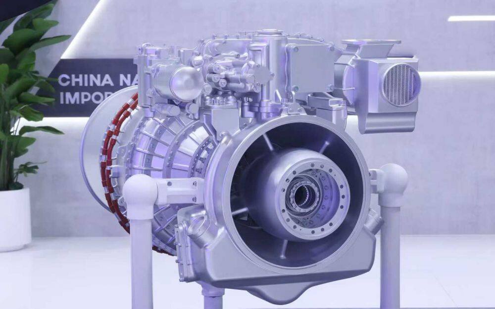
The hydrogen fuel cell engine model adopts a cross-sectional design, with a focus on showcasing the following core component structures:
Stack system: showcasing the arrangement of bipolar plates and membrane electrodes
Hydrogen circulation system: presenting the layout of hydrogen injectors and steam water separators
Air Supply System: Showcasing the Structure of Air Compressors and Humidifiers
Water thermal management system: presenting the layout of coolant circulation pipeline
Control component: Display the electronic control system and data acquisition module
The characteristic of the model is to display the internal structure through precise cutting angles, which is suitable for new energy exhibitions, education and training, and enterprise technology display scenarios.
2、 Material selection and characteristics
Main structural materials
Sectional shell: 6mm thick acrylic sheet (transparent/semi transparent), using hot pressing molding process
Metal components: aluminum alloy (stack shell), stainless steel (piping system)
Core components: Carbon fiber (bipolar plate), engineering plastics (membrane electrode)
Dynamic component: N20 deceleration motor (6RPM) drives fan rotation
Special functional materials
Transparent resin (displaying internal pipeline structure)
LED strip (simulating the brightness of the electrochemical reaction zone)
Magnetic connectors (convenient for modular disassembly and assembly)
3、 Core manufacturing process
Precision component manufacturing process
Stack fabrication:
CNC precision machining of bipolar plate flow channel
3D printed membrane electrode structure
Surface anti glare treatment
Hydrogen system production:
Laser cutting of hydrogen circulation pipeline
Transparent segment displays the structure of the injector
Simulating usage traces through aging treatment
Air system production:
Model making of micro compressor
Processing of transparent shell of humidifier
Surface metallic texture treatment
Assembly process flow
Install the fuel cell stack and internal components
Assembling hydrogen and air systems
Install control components and cooling system
Finally, install the sectional shell
4、 Post processing and coloring techniques
Surface treatment technology
Metallic texture: sprayed with metallic paint (primer color paint protective paint three-layer process)
Identification production: water sticker process with equipment nameplate added
Aging treatment: lightly polished edges to simulate usage marks
Color scheme design
Stack area: dark gray
Hydrogen System: Blue Label
Air system: Silver gray
Shell: Transparent Acrylic Original Color
Tags: industrial models, engine models, equipment model
