Aircraft engine model manufacturer
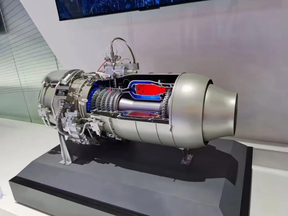
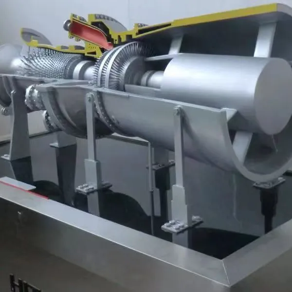
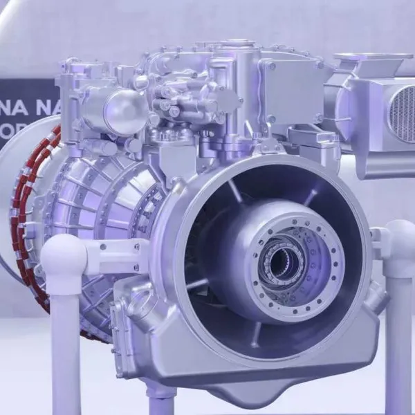
Scheme for making cross-sectional model of turbofan engine
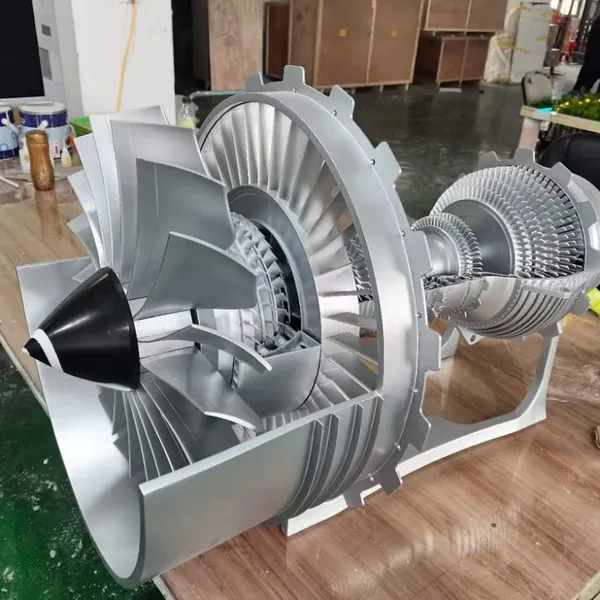
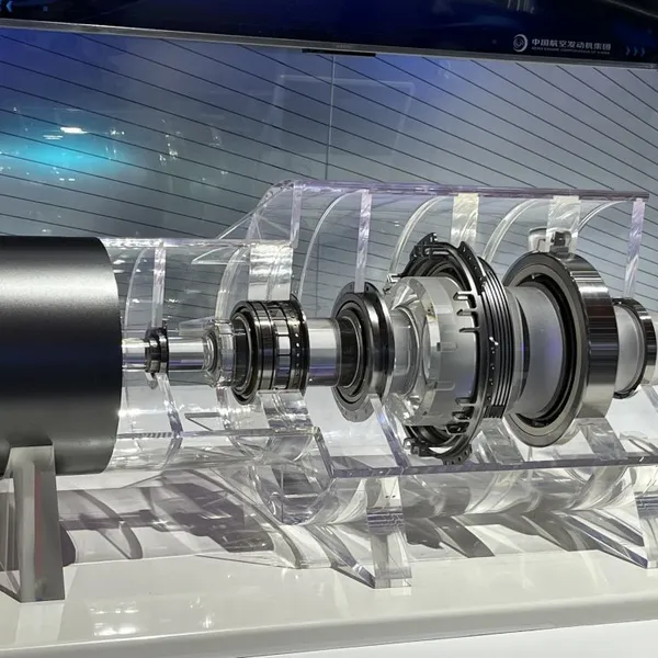
1、 Model display characteristics and design concept
This plan focuses on the cross-sectional model of turbofan engines and highlights the following core structural features:
Airflow channel system: Clearly present the complete airflow path from intake to exhaust
Compressor structure: display the arrangement and angle of multi-stage compressor blades
Combustion chamber layout: distribution structure of annular combustion chamber and fuel injector
Turbine system: blade array of high-pressure turbine and low-pressure turbine
Sectional design: Adopting a 30 ° oblique section scheme, showcasing the compressor, combustion chamber, and turbine simultaneously
The design concept of the model is to achieve a 90% structural restoration degree through precise cutting angles and material selection, while also considering the safety and display effect of international transportation.
2、 Material selection and characteristics
Main structural materials
Sectional shell: 6mm thick acrylic sheet (transparent/semi transparent), using hot pressing molding process
Metal components: aluminum alloy (compressor/turbine disc), stainless steel (shaft system)
Blade material: carbon fiber or aviation aluminum, ensuring lightweight and strength
Dynamic component: N20 deceleration motor (6RPM) drives fan rotation
Special functional materials
Transparent resin (displaying internal pipeline structure)
LED strip (simulating the brightness of the combustion zone)
Magnetic connectors (convenient for modular disassembly and assembly)
3、 Core manufacturing process
Precision component manufacturing process
Compressor production:
Five axis linkage machining center for producing axial flow blades
The centrifugal part adopts CNC precision machining
Surface anti glare treatment
Combustion chamber fabrication:
3D printing flame tube structure
Transparent section displays the layout of internal fuel injectors
Aging treatment simulates high-temperature usage traces
Turbine system:
Single crystal high-temperature alloy blade (simplified version)
The shaft system is made of 304 stainless steel
Weight balancing treatment
Assembly process flow
Install shaft system and internal components
Assemble compressor and turbine blades
Install combustion chamber and power output shaft
Finally, install the sectional shell
4、 Post processing and coloring techniques
Surface treatment technology
Metallic texture: sprayed with metallic paint (primer color paint protective paint three-layer process)
Identification production: water sticker process with equipment nameplate added
Aging treatment: lightly polished edges to simulate usage marks
Color scheme design
Compressor area: Silver gray
Combustion chamber area: orange red gradient
Turbine area: High temperature alloy gold color
Shell: Transparent Acrylic Original Color
5、 International Transportation Packaging Solutions
Protective packaging design
Modular packaging: decomposed into 3 independent modules (front/core/rear)
Cushion material: EVA foam customized lining+bubble film filling
Moisture proof treatment: built-in silicone desiccant and humidity indicator card
Transportation protection measures
Metal parts: PE film seal after applying rust proof oil
Electronic components: packaged in anti-static bags, separately fixed
Transparent component: pearl cotton wrapped to prevent scratching
Recently Posted
-
Production line equipment model manufacturing factory
September 11, 2025Case study on the production of miniaturized panoramic display models for industrial production lines1、 Overall planning and mater Read More
 -
Electronic production line model manufacturing factory
September 11, 2025Case study of high-precision display model production for electronic production line1、 Overall planning and material selectionThis Read More
 -
New energy charging station model manufacturer
September 11, 2025Case study on the production of high-precision display model (interactive lighting version) for new energy charging stations1、 Ove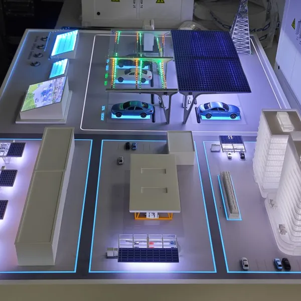 Read More
 -
Chemical equipment model making factory
September 11, 2025The entire process of making chemical reaction kettle models: "industrial grade restoration" from framework to details1、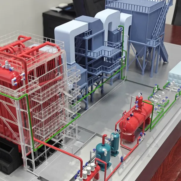 Read More

Contact Us
Recommended Products
-
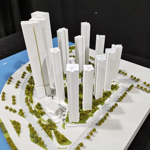
 Various Sand Table Model ManufacturersNegotiableMOQ: 1 Piece
 -
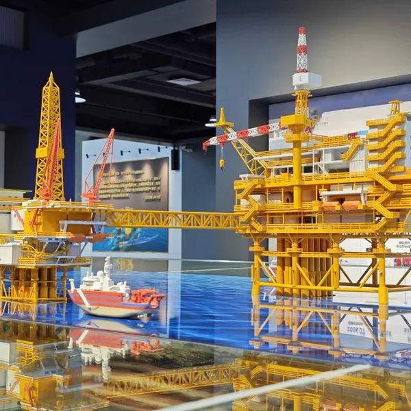
Offshore Oil Model Making FactoryNegotiableMOQ: 1 Piece
-
Aircraft Engine Model Manufacturing FactoryNegotiableMOQ: 1 Piece
-
Industrial Equipment Model Manufacturing FactoryNegotiableMOQ: 1 Piece
-
Industrial Sand Table Model Making FactoryNegotiableMOQ: 1 Piece
-
New Energy Sand Table Model ManufacturerNegotiableMOQ: 1 Piece
-
Building Sand Table Model ManufacturerNegotiableMOQ: 1 Piece
-
Semiconductor Equipment Model ManufacturerNegotiableMOQ: 1 Piece
-
Cooling Tower Model ManufacturerNegotiableMOQ: 1 Piece
-
Aircraft Engine Model ManufacturerNegotiableMOQ: 1 Piece
-
Engine Model ManufacturerNegotiableMOQ: 1 Piece
-
Building Sand Table Model ManufacturerNegotiableMOQ: 1 Piece
-
Blood Donation House Miniature Model ManufacturerNegotiableMOQ: 1 Piece
-
Chemical Model ManufacturerNegotiableMOQ: 1 Piece
-
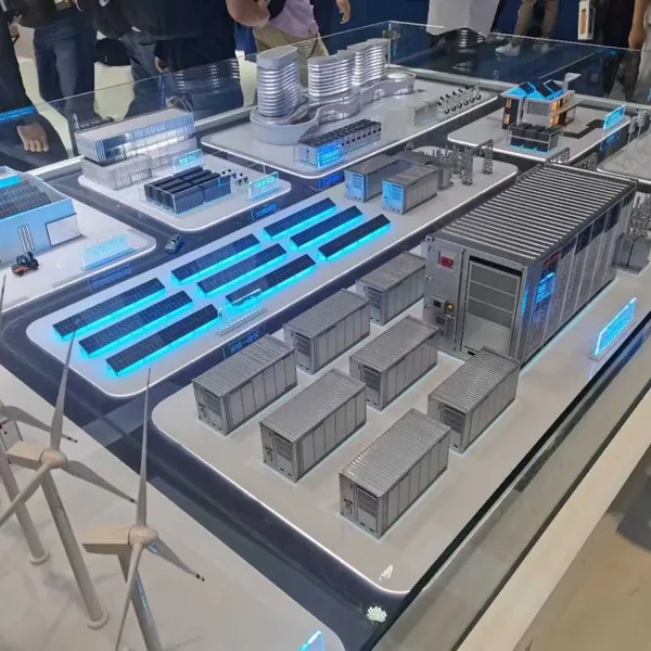
Manufacturer of Energy Storage Container ModelNegotiableMOQ: 1 Piece