
-
 yoyo
Hi there! Welcome to my shop. Let me know if you have any questions.
yoyo
Hi there! Welcome to my shop. Let me know if you have any questions.
Your message has exceeded the limit.
Engine model manufacturer
2025-09-10 14:51:35
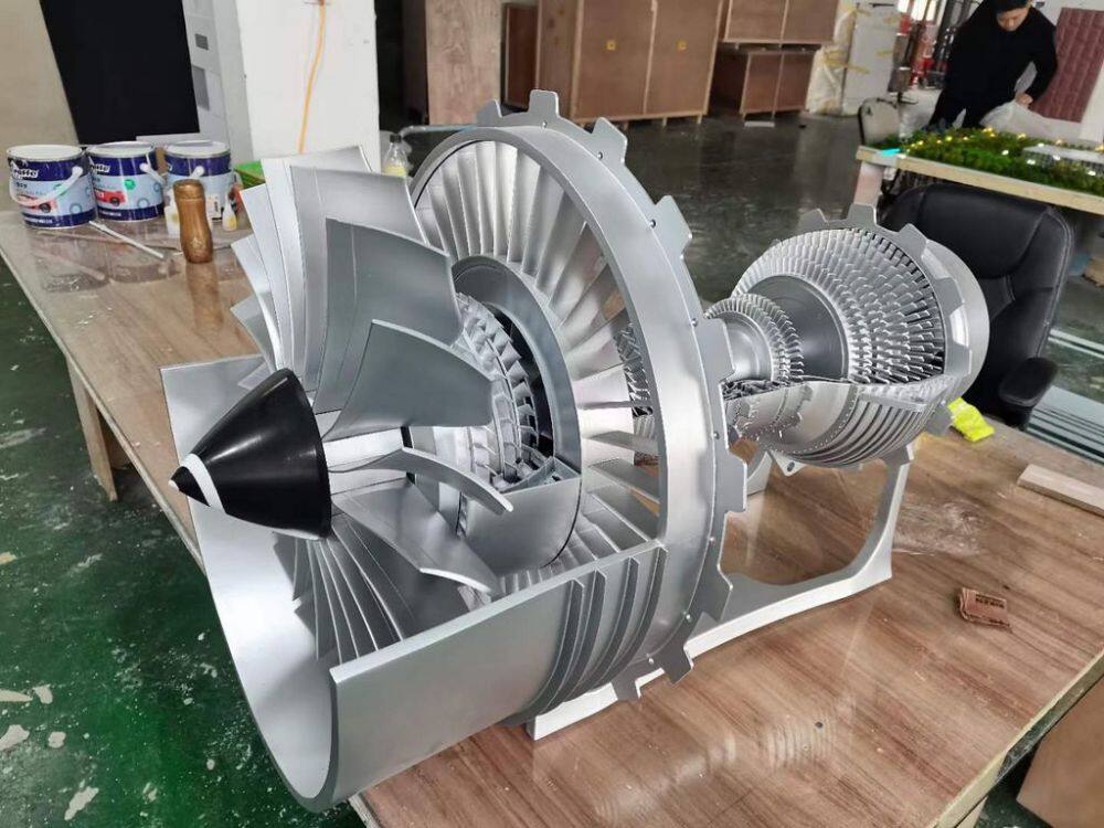
Model making scheme for aviation turbofan engine
1、 Model presentation elements and characteristics
The aviation turbofan engine model needs to showcase its internal structure and working principle, with core display elements including:
Fan System: Showcasing Large Fans and Their Blade Structures
Compressor: Angle and spacing of multi-stage compressor blades
Combustion chamber: flame tube and fuel injector model
Turbine system: blade array of high-pressure turbine and low-pressure turbine
Exhaust system: tail nozzle structure
Dual channel design: showcasing the airflow paths of the inner and outer channels
The characteristic of the model is to display the internal structure through sectional design, which is suitable for aviation exhibitions, education and training, and enterprise technology display scenarios.
2、 Material selection
Main structural materials
Shell: ABS engineering plastic or aluminum alloy, balancing lightweight and metallic texture
Blade: Carbon fiber or aviation aluminum, hot pressed to ensure accurate bending curvature
Compressor/turbine: CNC machining or high-precision 3D printing materials
Base: Wooden or metal frame to ensure stability
Special effect materials
Transparent acrylic (for sectional display)
Micro motor (drives fan rotation)
LED strip (simulating the brightness of the combustion zone)
3、 Production process
structural design
Cut open design: One side of the shell can be disassembled or replaced with transparent material to display the internal structure
Scale: commonly used 1:5~1:20 scale, retaining the core structure
Dynamic system: Micro motor drives fan rotation, combined with LED lighting to simulate combustion effect
Core component production
Fan and compressor: proportionally restore the angle and spacing of multi-stage blades
Combustion chamber: Create models of flame tubes and fuel injectors, with some models featuring transparent sections
Turbine and nozzle: blade microfabrication to maintain true streamline shape
Axis structure: Maintain structural integrity, even if it does not transmit real power
Assembly process
Install shaft system and internal components
Assemble compressor and turbine blades
Install combustion chamber and nozzle
Installation of shell and transparent panel with cut surface
4、 Post processing and coloring
Surface treatment technology
Metal paint spraying: using standard colors such as industrial gray and equipment blue, spraying in three layers (primer color paint protective paint)
Aging treatment: lightly polish the edges of the equipment to simulate usage marks
Identification production: Using water sticker technology to add equipment nameplates and safety signs
Dynamic effect implementation
Flow light effect simulates production rhythm
Breathing light display device in standby mode
Fault alarm red flashing prompt
Detail enhancement
The cable is made of thin copper wire to increase realism
The operation button adopts a micro switch, which can be actually pressed
The display area uses semi transparent acrylic to simulate LCD effect
Tags: industrial models, engine model, equipment model
