
-
 yoyo
Hi there! Welcome to my shop. Let me know if you have any questions.
yoyo
Hi there! Welcome to my shop. Let me know if you have any questions.
Your message has exceeded the limit.
Turboprop engine display model manufacturing factory
2025-09-10 14:57:53
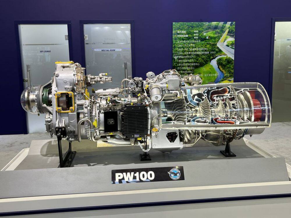
Model making scheme for PW100 series turboprop engine
1、 Model presentation elements and characteristics
The PW100 series turboprop engine model adopts a sectional design, focusing on showcasing the following core component structures:
Compressor system: showcasing the structure of an axial flow+centrifugal hybrid compressor
Combustion chamber: presenting a circular combustion chamber and fuel injector layout
Turbine system: blade array of high-pressure turbine and low-pressure turbine
Power output shaft: showcasing the connection structure between the reduction gear and propeller
Dual channel design: Clearly distinguish between cold and hot airflow channels
The characteristic of the model is to display the internal structure through precise cutting angles, which is suitable for aviation exhibitions, education and training, and enterprise technology display scenarios.
2、 Material selection
Main structural materials
Sectional shell: 6mm thick acrylic sheet (transparent/semi transparent), using hot pressing molding process
Metal components: aluminum alloy (compressor/turbine disc), stainless steel (shaft system)
Blade material: carbon fiber or aviation aluminum, ensuring lightweight and strength
Dynamic components: N20 deceleration motor (6RPM) drives fan rotation 7
Special effect materials
Transparent resin (displaying internal pipeline structure)
LED strip (simulating the brightness of the combustion zone)
Magnetic connectors (convenient for modular disassembly and assembly)
3、 Production process
structural design
Cutting Plan: Adopting a 30 ° oblique section design, showcasing the compressor, combustion chamber, and turbine simultaneously
Scale: 1:10 scale, retaining core structural features
Dynamic system: Micro motor drives fan rotation, combined with LED lighting to simulate combustion effect
Core component production
Compressor production:
Five axis linkage machining center for producing axial flow blades
The centrifugal part adopts CNC precision machining
Surface anti glare treatment
Combustion chamber fabrication:
3D printing flame tube structure
Transparent section displays the layout of internal fuel injectors
Aging treatment simulates high-temperature usage traces
Turbine system:
Single crystal high-temperature alloy blade (simplified version)
The shaft system is made of 304 stainless steel
Weight balancing treatment
Assembly process:
Install the shaft system and internal components first
Assemble compressor and turbine blades
Install combustion chamber and power output shaft
Finally, install the sectional shell
4、 Post processing and coloring
Surface treatment technology
Metallic texture: sprayed with metallic paint (primer color paint protective paint three-layer process)
Identification production: water sticker process with equipment nameplate added
Aging treatment: lightly polished edges to simulate usage marks
color scheme
Compressor area: Silver gray
Combustion chamber area: orange red gradient
Turbine area: High temperature alloy gold color
Shell: Transparent Acrylic Original Color
Tags: industrial models, engine models, Equipment model
